As a core power component widely used in construction machinery, water conservancy projects, and other heavy-duty applications, the performance of a hydraulic cylinder directly determines the operating accuracy, stability, and service life of the host equipment. How can factories build high-quality, stable-running hydraulic cylinders in 2026? This article systematically breaks down the manufacturing process, key technical points, quality control systems, and innovative applications involved in hydraulic cylinder production, taking you on a journey from raw material to finished precision product.
- Why Is Every Core Component of a Hydraulic Cylinder So Important?
- Machining Process of Core Components
- Quality Control and Inspection System
- Machining Equipment and Tool Selection
- Process Optimization and Innovative Applications
- Engineering Application Case
- Conclusion
- Discover More Reliable Hydraulic Cylinders at Cenbifyn
Why Is Every Core Component of a Hydraulic Cylinder So Important?

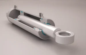
The reliable operation of a hydraulic cylinder depends on the coordinated performance of all its components. Among them, the cylinder tube, piston rod, piston, guide sleeve, and sealing elements are often referred to as the “five vital organs” of a hydraulic cylinder. Each plays a critical role, and their structural design and machining accuracy directly affect the overall performance of the cylinder.
(1) Cylinder Tube: The Pressure-Bearing Body and Motion Foundation
As the main structural body of a hydraulic cylinder, the cylinder tube is the primary pressure-bearing component and also provides precise guidance for the reciprocating motion of the piston. Its inner surface must allow smooth sliding of the piston, seals, and wear rings, which places extremely high demands on dimensional accuracy, geometric accuracy, and surface quality. Cylinder tubes are commonly made from high-quality materials such as No.20 steel or Q345B seamless steel pipes, providing sufficient strength and rigidity to withstand high hydraulic pressure without deformation or rupture.
(2) Piston Rod: The Key Carrier of Force Transmission
The piston rod connects the piston to external mechanical structures and is the core component for achieving linear motion and force transmission. Its performance directly determines the output efficiency and service life of the hydraulic cylinder. The piston rod must simultaneously meet requirements for high strength, wear resistance, and corrosion resistance, and is typically made from high-quality alloy structural steels such as 45# steel or 40Cr. The key technical challenges lie in controlling straightness, outer diameter accuracy, surface hardness, and extremely low surface roughness, in order to minimize seal wear and ensure long-term leak-free operation.
(3) Piston: The Hub of Hydraulic-to-Mechanical Energy Conversion
The primary function of the piston is to withstand hydraulic pressure and convert hydraulic energy into mechanical energy. Driven by hydraulic oil pressure, it performs reciprocating motion to operate external equipment. Since the piston must strictly separate the hydraulic oil in the two chambers of the cylinder, its outer diameter accuracy, sealing groove tolerances, and surface quality are critical to sealing performance. Common materials include 45# steel, cast iron, and copper alloys. During machining, special attention must be paid to sealing groove dimensions and surface roughness to ensure perfect compatibility with sealing elements.
(4) Guide Sleeve: Precision Guidance for Stable Operation
The guide sleeve is installed at the front end of the cylinder tube and mainly provides support and guidance for the piston rod, ensuring stability and coaxiality during reciprocating motion. Its inner surface typically accommodates seals, guide rings, and dust seals, and must meet requirements for guiding accuracy, wear resistance, and sealing protection. Common materials include 45# steel and ductile iron. The machining focus lies in controlling the dimensional accuracy, roundness of the guide bore, and its fit with the cylinder tube.
(5) Sealing Elements: The Core Guarantee of Leak-Free Operation
Although sealing elements are auxiliary components, they are critical to ensuring leak-free operation of hydraulic cylinders. They must maintain reliable sealing performance under high pressure and reciprocating motion, while also offering wear resistance and oil corrosion resistance. The machining quality of sealing components directly affects leakage rates and service life, requiring precise matching with piston and guide sleeve sealing grooves. Therefore, extremely strict requirements apply to groove dimensions, chamfers, and fillet radii.
Machining Process of Core Components
The machining of hydraulic cylinder components follows the principle of “step-by-step progression and meticulous refinement.” From raw material preparation to final inspection, strict process standards are established at every stage to ensure that the finished products fully meet design requirements.
(1) Pre-Machining Preparation: Laying a Solid Quality Foundation
Material Selection and Inspection:
Materials are selected according to the functional requirements of each component. For example, piston rods typically use 45# steel or 40Cr alloy steel, while cylinder tubes are made from No.20 seamless steel pipes or Q345B steel pipes. After raw materials enter the factory, chemical composition analysis, mechanical property testing, and non-destructive testing are carried out to detect internal defects and ensure that the materials meet machining requirements.
Drawing Review and Process Planning:
Engineering drawings are carefully reviewed to clarify key technical requirements such as dimensional accuracy, geometric tolerances, and surface roughness. Based on available equipment capabilities, an optimal machining plan is developed, defining machining sequences, processing methods, and tooling and fixture arrangements. For example, piston rod machining requires proper planning of the sequence and parameters for quenching and tempering, turning, grinding, and chrome plating processes.
Equipment and Tool Preparation:
High-precision machining equipment such as CNC machines, grinders, and honing machines are selected according to processing requirements, and their accuracy is calibrated to ensure that machine precision exceeds part tolerance requirements. Specialized cutting tools, fixtures, and measuring instruments—such as carbide tools, dedicated positioning fixtures, and coordinate measuring machines (CMMs)—are also prepared to guarantee machining accuracy.
(2) Piston Rod Machining Process: Dual Focus on Surface Hardness and Precision
As a moving component, the piston rod has the most complex machining process and must undergo multiple precision operations. The process focuses on three core objectives: strength enhancement, precision control, and surface protection.
Cutting:
Round steel raw materials are cut by sawing or shearing according to part dimensions, ensuring sufficient machining allowance is retained on the blank.
Quenching and Tempering:
The cut blanks undergo quenching and tempering (quenching followed by high-temperature tempering) to improve the overall mechanical properties of the core material, ensuring sufficient strength and toughness to withstand operational loads. For high-precision products, induction hardening or combined quenching–induction processes may be applied to further enhance material performance.
Straightening:
Because heat treatment may cause deformation, straightening is performed to correct rod straightness, providing a precise foundation for subsequent machining.
Turning:
Turning is divided into rough turning and finish turning. Rough turning removes most excess material to form the basic shape, while finish turning strictly controls outer diameter accuracy and surface roughness, providing a stable reference for grinding. After finish turning, the outer diameter tolerance must be controlled within ±0.03 mm.
Pre-Chrome Grinding:
Centerless grinding is applied to the piston rod outer surface to further improve dimensional accuracy and surface finish, ensuring strong adhesion of the chrome layer. After grinding, surface roughness must reach Ra ≤ 0.4 μm, and straightness error must be controlled within 0.01 mm per 100 mm.
Hard Chrome Plating:
A hard chrome layer is deposited on the piston rod surface through electroplating, with thickness strictly controlled between 30–50 μm to ensure surface hardness of HV ≥ 800, significantly improving wear and corrosion resistance. For special conditions such as humid environments, HVOF high-velocity oxygen fuel spraying combined with plasma spraying may be used to further enhance corrosion and wear resistance, meeting the stringent requirements of water conservancy projects.
Post-Plating Polishing / Superfinishing:
The chrome-plated surface is polished to reduce surface roughness to Ra ≤ 0.2 μm, minimizing friction and wear with sealing elements and extending seal service life. After superfinishing, the rod surface must be free of scratches, pits, or other defects.
(3) Cylinder Tube Machining Process: Ultimate Refinement of Inner Bore Accuracy
The core of cylinder tube machining lies in precision processing of the inner bore, which must simultaneously meet requirements for dimensional accuracy, geometric accuracy, and micro-surface geometry to provide an ideal operating environment for piston movement.
Cutting and Straightening:
Cold-drawn tubes are selected as raw materials and cut according to cylinder length requirements. Straightening is then performed to correct tube bending and ensure straightness meets machining requirements.
Heat Treatment (Quenching and Tempering):
The cylinder tube blank undergoes quenching and tempering to improve strength and toughness, enhancing its ability to withstand high pressure and preventing deformation or rupture during operation.
Rough Turning:
The outer diameter and end faces of the cylinder tube are rough-turned to remove surface scale and excess material, preliminarily defining basic dimensions and preparing for subsequent welding and finishing processes.
Welding Process:
According to structural design requirements, flanges, oil ports, and other components are welded onto the cylinder tube. Welding temperature and speed are carefully controlled to avoid deformation and defects. Non-destructive inspection is conducted after welding.
Inner Bore Finishing:
Scraping or honing is used for precision machining of the cylinder bore, which is the most critical step in cylinder tube processing. Honing forms a cross-hatched pattern on the bore surface through rotational and reciprocating motion of the honing head. This pattern helps retain lubricating oil, reduces friction between piston and bore, and extends seal life. After machining, bore tolerance must meet H7 grade, with roundness and cylindricity errors ≤ 0.005 mm and surface roughness Ra ≤ 0.2 μm.
Oil Port Polishing:
Dedicated polishing is performed on oil ports. Ports with diameters < 25 mm are polished using leather grinding heads, while ports > 25 mm are first rough-ground with abrasive heads and then fine-polished using hemispherical cloth wheels. This ensures smooth, burr-free oil ports, preventing flow resistance or seal damage.
Cleaning and Inspection:
After machining, the cylinder tube is thoroughly cleaned to remove internal chips, oil, and burrs, ensuring cleanliness requirements are met. Dimensional inspection and non-destructive testing are then performed to detect internal defects.
Quality Control and Inspection System
The machining accuracy of hydraulic cylinder components directly determines the overall performance of the hydraulic cylinder. Therefore, a full-process and multi-level quality control and inspection system has been established, implementing strict control at every stage from raw materials to finished products.
(1) Quality Control Standards
Dimensional Accuracy Control:
All dimensional tolerances strictly comply with engineering drawings. Linear dimensional tolerances are implemented in accordance with GB/T 1804-2000 standards: for basic dimensions >30–120 mm, tolerances are controlled within ±0.3 mm; for >120–400 mm, tolerances are controlled within ±0.5 mm. Geometric tolerances are implemented according to GB/T 1184-1996 standards. Roundness and cylindricity tolerances are determined based on basic dimensions and accuracy grades, with geometric tolerances of critical surfaces controlled at ≤0.005 mm.
Surface Quality Standards:
The surface roughness of piston rods shall be Ra ≤0.2 μm, cylinder bore Ra ≤0.2 μm, piston outer diameter Ra ≤0.8 μm, and guide sleeve inner bore Ra ≤0.8 μm. Surfaces must be free from scratches, pitting, scale, and other defects, and the chrome plating layer shall show no peeling or flaking.
Material Performance Requirements:
The surface hardness of piston rods shall be ≥HRC 50–56 (with an induction-hardened layer depth of 2–3 mm), and the core hardness shall be ≥HB 220–250. Cylinder tube materials shall have a tensile strength ≥490 MPa and yield strength ≥245 MPa. The hardness of piston and guide sleeve materials shall be ≥HB 180–220.
Special Operating Condition Requirements:
For components used in humid environments such as hydraulic and water conservancy projects, salt spray testing is required to ensure corrosion resistance with no rusting for more than 1,000 hours. For components operating in multi-cylinder synchronized systems, the synchronization error shall be ≤15 mm.
(2) Key Inspection Methods and Equipment
Dimensional Accuracy Inspection:
Coordinate Measuring Machine (CMM):
Used for precision measurement of critical dimensions and geometric tolerances, with measurement accuracy up to ±0.001 mm. It enables comprehensive inspection of three-dimensional dimensions, roundness, cylindricity, concentricity, and other parameters to ensure compliance with design requirements.
Outside Micrometers and Dial Bore Gauges:
Used for on-site inspection of outer diameters and inner bores, offering convenient operation with measurement accuracy up to ±0.001 mm.
Levels and Straightness Measuring Instruments:
Used to inspect straightness errors of piston rods and cylinder tubes, ensuring compliance with motion accuracy requirements.
Surface Quality Inspection:
Surface Roughness Tester:
Directly measures surface roughness and displays Ra, Rz, and other parameters in real time to ensure compliance with surface quality standards.
Visual Inspection System:
Captures high-resolution images of component surfaces via HD cameras and automatically identifies defects such as scratches and pitting, improving inspection efficiency and accuracy.
Coating Thickness Gauge:
Used to measure the chrome plating thickness of piston rods, ensuring a coating thickness of 30–50 μm to guarantee wear resistance and corrosion protection.
Material Performance Inspection:
Hardness Testers:
Rockwell hardness testers are used for surface hardness measurement, while Brinell hardness testers are used for core hardness testing, ensuring compliance with material hardness requirements.
Tensile Testing Machine:
Used to conduct tensile tests on raw materials and finished products to evaluate tensile strength, yield strength, and other mechanical properties, verifying material quality.
Impact Testing Machine:
Used to evaluate the impact toughness of materials, ensuring that components do not fracture under impact loads.
Non-Destructive Testing (NDT):
Ultrasonic Testing (UT):
Used to detect internal defects such as cracks, porosity, and inclusions, particularly suitable for internal quality inspection of critical components like cylinder tubes andMagnetic Particle Inspection (MPI):
Applied to ferromagnetic materials to detect surface and near-surface defects such as cracks and scratches, offering high sensitivity and convenient operation.
X-ray Inspection:
Used to inspect internal defects in welded parts and castings, capable of detecting micro-cracks and internal inclusions to ensure structural integrity.
Machining Equipment and Tool Selection
High-precision machining equipment and properly matched tools are the foundation for ensuring component machining quality. According to the processing requirements of different components, specialized machining equipment and tools are configured accordingly.
(1) Core Machining Equipment
CNC Machine Tools:
Including CNC lathes, CNC milling machines, and machining centers, these machines provide high-precision and high-efficiency machining capabilities. CNC lathes are used for turning operations of piston rods, pistons, and guide sleeves, with positioning accuracy up to ±0.002 mm and repeat positioning accuracy of ±0.001 mm. Machining centers are applied to multi-face machining of complex structural components, enabling multiple processes to be completed in a single setup and reducing clamping errors.
Grinding Equipment:
Centerless grinders, external cylindrical grinders, and internal cylindrical grinders are used for precision finishing of components. Centerless grinders are applied to grinding the outer diameter of piston rods, achieving grinding accuracy up to IT6 grade and surface roughness Ra ≤0.4 μm. Internal cylindrical grinders are used for grinding the inner bores of cylinder tubes and guide sleeves to ensure bore dimensional accuracy and roundness. Honing machines are applied to cylinder bore honing, achieving high-precision and low-roughness internal surface finishes.
Special Processing Equipment:
Including chrome plating equipment, coating equipment, and heat treatment equipment. Chrome plating equipment adopts high-precision electroplating processes to ensure coating uniformity and adhesion strength. HVOF (High Velocity Oxygen Fuel) supersonic spraying equipment is used for surface treatment of components operating under special conditions, enhancing corrosion resistance and wear resistance. Heat treatment equipment includes quenching and tempering furnaces and high-frequency induction hardening machines, ensuring stability and consistency of heat treatment processes.
Auxiliary Processing Equipment:
Drilling and milling machines, sawing machines, straightening machines, and cleaning machines provide auxiliary support for various machining stages. For example, drilling and milling machines are used for drilling and tapping operations, straightening machines are applied to correct straightness deviations of components, and cleaning machines are used for post-machining component cleaning.
(2) Tool Selection and Application
Cutting Tool Material Selection:
Cutting tools are selected according to the characteristics of the machined materials. High-speed steel (HSS) tools are used for machining common steels such as 45# steel and 40Cr. For high-strength alloy materials or high-precision machining, carbide tools are selected to improve cutting efficiency and tool life. For heat-treated workpieces with high hardness, cubic boron nitride (CBN) tools are used to ensure cutting performance.
Cutting Tool Geometry Design:
Cutting tool parameters are adjusted according to machining processes. During turning operations, rake angles are selected within 5°–15°, and clearance angles within 8°–12° to ensure smooth cutting. During grinding operations, grinding wheel grit sizes of 60#–120# and medium-to-soft hardness grades are selected to avoid surface burning of the workpiece.
Special Fixture Configuration:
Special fixtures are designed for key components. For example, piston rod machining adopts double-center positioning fixtures to ensure workpiece stability and coaxiality during machining. Cylinder tube machining uses centering fixtures to prevent deformation during clamping. Fixture positioning accuracy is controlled at ≤0.005 mm to ensure machining errors remain within allowable limits.
Measuring Tool Configuration:
In addition to coordinate measuring machines (CMM), conventional measuring tools such as outside micrometers, dial bore gauges, depth gauges, and angle gauges are configured, along with specialized inspection instruments including surface roughness testers, hardness testers, and coating thickness gauges, to meet inspection requirements at different stages. All measuring tools are regularly calibrated to ensure measurement accuracy.
Process Optimization and Innovative Applications
With the continuous expansion of hydraulic cylinder application fields, higher requirements are imposed on component machining processes. Through ongoing process optimization and technological innovation, machining accuracy, production efficiency, and product reliability are continuously improved to meet the application demands under various operating conditions.
(1) Process Flow Optimization
Reduction of Machining Steps:
By combining processes or adopting multifunctional machine tools, machining workflows are shortened. For example, turn-grind composite machine tools are used to complete turning and grinding of piston rods in a single setup, reducing the number of clamping operations, minimizing clamping errors, and improving machining efficiency.
Optimization of Process Sequence:
The process sequence is adjusted according to the machining characteristics of components. For example, in piston rod machining, quenching and tempering are carried out immediately after blanking to avoid subsequent machining affecting heat treatment results. In cylinder tube machining, welding is arranged after rough turning, facilitating subsequent finishing operations to correct welding deformation.
Introduction of Online Measurement Technology:
Online measurement systems are installed on key machining equipment to monitor machining dimensions in real time and adjust process parameters promptly, thereby reducing rework rates. For example, laser diameter gauges are installed on CNC lathes to measure piston rod outer diameters in real time and automatically compensate for tool wear, ensuring stable dimensional accuracy.
(2) Application of Innovative Technologies
High-Precision Machining Technologies:
Ultra-precision grinding and honing technologies are adopted to further enhance dimensional accuracy and surface quality of components. For example, precision honing is applied to cylinder bores, achieving surface roughness Ra ≤0.1 μm and roundness error ≤0.003 mm, meeting the requirements of high-end hydraulic cylinders.
Innovation in Surface Treatment Technologies:
In addition to conventional chrome plating processes, advanced surface treatment technologies such as HVOF (High Velocity Oxygen Fuel) supersonic spraying and plasma spraying are introduced to deposit wear-resistant and corrosion-resistant coatings including WC-Co and Al₂O₃. Coating hardness can reach HV ≥1200, significantly enhancing corrosion resistance, making them suitable for humid and highly corrosive working environments, such as piston rods of hydraulic gate hoists used in Pinglu Canal water conservancy projects.
Automation and Intelligent Machining:
Automated production lines are established by integrating CNC machine tools, robots, and logistics systems to achieve automated machining, inspection, and handling of components. PLC control systems are applied to precisely regulate machining parameters and enable coordinated operation of multiple devices, improving production efficiency and machining consistency. For example, automated piston rod production lines realize full-process automation from blanking, quenching and tempering, turning, and grinding to chrome plating and polishing, increasing production efficiency by more than 30% and reducing machining errors by 20%.
Application of 3D Printing Technology:
During the product development stage, 3D printing technology is used to rapidly fabricate prototypes of components such as pistons and guide sleeves, shortening development cycles. For certain components with complex structures, metal 3D printing is applied for direct manufacturing, enabling complex structural designs that are difficult to achieve through traditional machining while reducing processing steps and material waste.
(3) Common Issues and Solutions
Insufficient Machining Accuracy:
Issues such as dimensional deviations and excessive geometric tolerances are addressed through measures including regular calibration of machining equipment, optimization of cutting tool parameters, and improvement of clamping methods. For example, CNC machines undergo periodic geometric accuracy inspection and compensation to ensure machine precision; elastic fixtures are adopted to reduce clamping deformation; and cutting parameters are optimized to minimize the impact of cutting forces on machining accuracy.
Surface Quality Defects:
Surface defects such as scratches, pitting, and excessive roughness are resolved by improving the machining environment, optimizing tool selection, and strengthening process protection. For example, maintaining a clean machining environment prevents chips from scratching workpiece surfaces; sharp cutting tools are selected to reduce burr formation; and timely rust-prevention treatment is applied after machining to avoid oxidation and corrosion.
Non-Uniform Material Properties:
Issues such as inconsistent material hardness and fluctuations in mechanical properties are addressed by strengthening raw material inspection and adopting segmented heat treatment processes. For example, increased hardness sampling is conducted upon raw material arrival to ensure uniformity, and staged heating and soaking are applied during heat treatment to ensure uniform overall hardness of components.
Multi-Cylinder Synchronization Errors:
For applications involving coordinated operation of multiple hydraulic cylinders, such as gate hoists in water conservancy projects, proportional variable pump control combined with dual-sensor monitoring (ceramic rod sensors + external static magnetic grating displacement sensors) and precise PLC regulation is adopted. This enables a “slow–fast–slow” variable-speed operating mode, ensuring synchronization errors are controlled within ≤15 mm.
Engineering Application Case
As a strategic project under China’s “Belt and Road” Initiative, the Pinglu Canal imposes extremely high requirements on the hydraulic gate hoists of the Madao Hub (right line) navigation lock. The system must maintain stable operation in long-term humid environments, with multi-cylinder synchronization errors controlled within ≤15 mm. For this project, the hydraulic cylinder manufacturer supplied 20 complete hydraulic cylinder assemblies, whose core component machining processes fully reflect the technical principles described above:
Piston Rod
The piston rods are manufactured from 40Cr steel and undergo quenching and tempering followed by high-frequency induction hardening. The surface is treated using HVOF (High Velocity Oxygen Fuel) supersonic spraying technology, with a coating thickness of 50 μm and hardness of HV ≥1000. Corrosion resistance has been verified through a 1,000-hour salt spray test, making the piston rods fully suitable for the humid canal environment.
Cylinder Tube
The cylinder tubes are made from Q345B seamless steel pipes and processed through rough turning, welding, and honing operations. The bore dimensional accuracy reaches H7 grade, with roundness controlled within ≤0.004 mm. The internal surface features an optimized cross-hatch pattern, ensuring smooth piston movement and extending seal service life by 50%.
Guide Sleeve
The guide sleeves are manufactured from ductile cast iron. The guide bore machining accuracy reaches H7 grade, and when combined with high-precision sealing components, ensures piston rod motion coaxiality within ≤0.01 mm, significantly reducing wear.
Multi-Cylinder Synchronization Control
Multi-cylinder synchronization control is achieved through proportional variable pump control combined with dual-sensor monitoring and precise PLC regulation, enabling synchronization errors to be controlled within ≤10 mm and meeting the high-precision requirements of gate opening and closing operations.
This batch of hydraulic gate hoists underwent multi-stage acceptance processes, including documentation review, on-site measurement, and functional verification. All performance indicators met contractual and engineering standard requirements, and the systems have been successfully applied at the Pinglu Canal Madao Hub, providing reliable hydraulic power assurance for this landmark infrastructure project.
Conclusion
The machining processes of hydraulic cylinder components constitute a comprehensive technology that integrates materials science, mechanical manufacturing, and precision measurement. Its development has consistently focused on the goals of higher precision, superior performance, longer service life, and lower cost.
From raw material selection to finished product inspection, and from traditional machining to intelligent manufacturing, continuous refinement at every stage drives the overall performance improvement of hydraulic cylinders.
Discover More Reliable Hydraulic Cylinders at Cenbifyn
In today’s era of rapid development in high-end equipment manufacturing, hydraulic cylinders, as core power components, are being widely applied across an expanding range of fields, including construction machinery, water conservancy projects, and aerospace.
We will continue to focus on innovation in machining processes, consistently introducing advanced technologies and equipment while optimizing our quality control systems. Through more precise manufacturing and more reliable performance, we aim to provide high-quality hydraulic cylinder components to customers worldwide, supporting major national engineering projects and the high-quality development of the high-end equipment manufacturing industry.